Showing posts with label Restoration. Show all posts

Wednesday, 25 August 2021

Twist of Lemon

I’ve been experimenting with a fabled rust remover rumored for generations to yield miraculous clensing powers …lemon juice! I wanted to clean up my VIN plate in the most gentle way possible and restore the shine of the original metal. I carefully removed my VIN plate (yes, I know it is kind of a grey area when it comes to legality) by gently grinding down the rear of the rivets using the Dremel. I then used a small punch to tap the rivets out using barely any force. I then began juicing my bag of lemons:


I used a fine sieve to remove the piff (not sure this step was necessary, but I was on a roll) and poured into a suitably sized container:


I left my VIN plate submerged for about 48 hours and then wiped away the crud using a toothbrush. I was happy with the initial results:


To finish off I vigorously polished with some Autosol followed by Silvo:


It is a shame that the following photo cannot accurately convey just how shiny this thing turned out. Believe me, it is like a mirror now:

Tuesday, 29 August 2017

DIY Powder Coating

What, no posts for two whole months ...what gives?! Well, I assure you that I have been progressing the car on several fronts, but I just keep coming up against panel alignment issues and other such demotivating frustrations, hence why I have not posted for a while. To reignite my enthusiasm I decided to focus my energy on something else for a change and thought it would be fun to turn my hand to power coating. I've always loved the way things looked in powder coat, but I didn't actually know anything about the process until doing it. I find that getting actively involved is often the best way to learn. 

To start with I spent an eternity methodically sandblasting and degreasing all of these miscellaneous components:


I then masked off certain areas using high temperature polyester tape and silicone plugs.

A word of caution: I ordered the masking plugs off of eBay whilst at work. I do not recommend searching for the particular key words 'silicone + plug' whilst visible to passing colleagues in an open plan office ...ohh, sh*t! Delete screen, DELETE SCREEN!

Using latex gloves to avoid contamination, I careful packed the parts into a paper lined shoebox and took them half a mile up the road to the workshop of my buddy Chris at 'Moody Moto'. He hand builds some incredible custom chopper motorbikes based around old Ducati engines and is one talented mofo (check out his sublime handiwork here). Anyway, he happens to have a basic powder coat setup and an repurposed domestic oven in his workshop for baking the parts. I bribed him with a pack of beers and set about it.

I hung the parts using conductive wire (thick welding wire in this case) from the removable oven shelf:


I opted for a black (RAL 9005) semi-gloss polyester coating manufactured by Interpon. I was concerned that full 'mirror' gloss might leave the parts looking a bit over-restored, so a more satin finish felt appropriate for my needs. The application of the powder was actually pretty simple. Once the electrode of the gun was attached to the metal shelf, the powder was liberally sprayed over the parts in a wafting motion. The electrostatic process attracts the powder particles to the charged parts leaving a layer of powder evenly distributed across the surfaces. I did it in 3 batches to avoid overcrowding and to ensure I could angle the gun sufficiently to coat all of the parts sufficiently:


Carefully the fragile dry coated parts were transferred to the preheated oven and were baked at 180 degrees for around 20 mins. Here is the magic result:


Look at that tasty serial number, so crisp:


A few more to feast your eyes on:


I am beyond pleased at the outcome as the cured finish exceeded my expectations. About 85% of the parts came out faultless and the remainder will need some minor touching up. Not bad for a first go! I have plenty of powder left and a few more parts that I think I will blast and coat in the near future; it would be rude not to!

Big thanks to Chris for allowing me to use his gear and guiding me through the process!

Wednesday, 5 April 2017

Repairing the original accelerator pedal

It would have been quick and convenient to simply replace the old accelerator pedal with a remanufacted one. However, I am keen to keep all of the tactile control services original as I believe they embody the historical ‘soul’ of the car. When I am eventually driving the car again I want the satisfaction of knowing that I am pressing on the same pedals that were operated by all of Gretchen’s former owners  since the day she left the VW dealership.

The accelerator pedal was in a bit of a sorry state, with the bottom section having been hacked off by a previous owner (after it started to rot away I am guessing). A door hinge was instead bolted on and welded to the floor in a ramshackle fashion. It was unsightly and not at all smooth to operate. Occasionally when driving the pedal would jam solid if depressed too far. Not particularly good or safe!

I took the later ‘roller ball’ donor pedal that I recently scored for a fiver at Dubfreeze and compared it against my original and decided how best to join the two together:


After careful measuring I cut the required bottom section off of the donor pedal:


Marked up a corresponding cut line on my original pedal and trimmed down accordingly:


Got the two pieces and aligned them on a flat sturdy piece of copper backer:


After tacking the sections in place from behind I unclamped and double checked everything was correctly aligned before fully welding from the front side. Had to crank up the amps on the welder to ensure good penetration as the steel is quite thick:


After linishing back I reached for my new magic toy, a 5" Random Orbit Sander:


I am so impressed with the way that this thing finishes the metal. It really helps smooth out and blend the repaired area given an almost invisible finish (assuming that prior care has been taken with panel alignment etc):


After a lick of zinc primer I measured out the correct location for the 6mm hole. I don’t think this serves any particular purpose, but who am I to argue with the wisdom of VW:


All finished and looking like a functional whole once again:


Wednesday, 24 June 2015

Napoleon fix-up (part 1)

A turning point has been reached as things are now very slowing starting to go back together! Because this blog post documents the first significant metalwork repair on the car, I have opted to covered it in step-by-step detail (don't worry, im not going to be as obsessive about describing every single minor repair in the future!). I shall publish this task in several parts as I progress, just to make it more digestible. 

Enough of the intro, lets jump into the action.... 

Repairing the Naps hat from the previous 'balls-up' has been weighing on my mind ever since the incident. You may recall from this previous post that I had ended up with a rather large gap between the old metalwork and the repair section due to poor judgment on my part. Since that time I have attempted to make various repair sections, but the arbitrary angles have caused nothing but frustration and poor alignment. I needed to simply things and approach this from a different angle (pun not intended). So, I decided to recut the remaining naps hat at a 90 degree angle to the diagonally sloping top edge. Here is the proposed angle marked with gaffer tape:


Checking for accuracy using a set square;


Once cut and neatened up I was confident that I had an angle that I could trust. It was a known quantity:


The main reason that I failed initially was that I had not focused on keeping the bottom edge of the repair straight and true. So, I figured that making a jig was the way to go this time. Essentially, I joined 2 pieces of scrap box section together using spot welds on one side and beads on the other. With the beads ground down and a lick of primer added I had a nice flat area:


I then made a paper template stencil with the bolt holes carefully mapped out to match the factory dimensions (with additional cross-hairs to visually assist with alignment). Also marked out some guides for aligning the jig with the chassis tunnel:


A quick spray of red primer to contrast against the grey:


....and the jig was good to go:


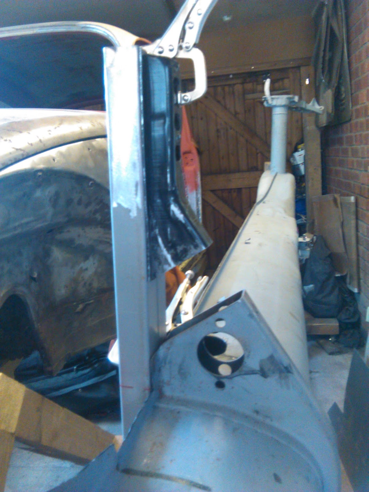
With the jig clamped into place on the chassis, I was provided with a solid foundation to work from. I trimmed up the end of the repro panel (again at 90 degrees to the sloping diagonal) and positioned it on the jig, clamping it into place. This allowed me to accurately assess the missing gap that I needed to fabricate:


Once measured up I cut out the repair section from fresh 2mm thick steel. Before bending the patch into shape, I knocked up a diy former to ensure that the outer profile of the piece would accurately match the original. I then put the whole lot into a vice and when I was sure everything was lined up correctly I proceeded to progressively tap the piece over with a rubber mallet:


 This created a good 90 degree bend with a suitable bend radius:


The fabricated piece all clamped up, aligned and ready for the welding to commence:


After countless hours playing with the settings on my new welder to ensure adequate penetration, I was finally confident to make the first tack weld of this resto - a significant milestone:


All of the tacks in place just prior to filling in the spaces in-between with a series of stich welds. To mitigate any heat warping, I filled up my compressors and used the air gun to blast a jet of cool air onto the hot welds:


Once it was all fully welded up I carefully ground the welds down dressed the area to make the new section blend seamlessly. Also rough cut the excess away from the bottom edge of the new piece:


Lining up the end section cut from the repro panel:


and here it is all welded in:


....and ground down nice & flush:


Seeing this section coming together has been really motivating and has boosted my confidence no end. You know, I reckon I can do this! 

Coming up in Part 2: I shall be cutting the bottom sections flush with the jig ready to accept newly fabricated flanges, drilling a few holes and more... Oooooh, the suspense!

Tuesday, 30 September 2014

Back to the pan

So much of my time lately has been absorbed in researching, thinking and planning the next stages of the resto. However, I think it has been necessary for me to take a back step, reassess the priority areas and unblock some issues that were preventing me progressing. Ultimately I concluded that I needed to refocus my attention on the chassis and crack on with maximum vigor! Firstly, I had a brain dump and wrote out a check list (in no particular order) of all the odd jobs that need doing before the chassis would be ready for paint: 


I have now set myself up with a decent supply of Argon/C02 welding gas: 


With a new regulator fitted and plumbed into the MIG welder. It works like a dream:


The WW floor pan halves that I bought a while back were designed for a LHD car and I needed to consider how I would go about converting them to RHD and make it correct for for a '65 pedal assembly setup. Through my research it became apparent that there should be a small strengthening/reinforcement plate which supports the pedals. Some bugs appear to have this strengthening plate visible on the top side of the floor pan, but there was no trace of this when I dismantled the components from the old pan. Strange I thought... then I recalled cutting through what I thought was an old scabby repair patch last year and realised that it was actually the reinforcement plate (the layers of rusted crud were masking its true identity!). An intensive search on Google images and various VW forums confirmed that the plate sits underneath the pan on the '65 model. Luckily I have been retaining all the old scrap cut from the car to use for welding practice. This was this old chunk that I was looking for: 


I chiseled off all of the rust flakes and it all became obvious:

The plate itself is basic enough, so I will be making a new one out of 5mm flat bar. The long edge is basically seam welded to the point where the edge of the Naps hat and bottom plate meet. The short edge is seam welded to the lip of the chassis tunnel and there are also a series of spot welds that fasten the floor pan to the strengthening bar. The two (threaded) holes in the middle are for the mounting brackets, which sit on top of the pan – which is fortunate as it means that I will just needed to drill 2 holes in the new drivers side floor pan in order to adapt it to RHD.

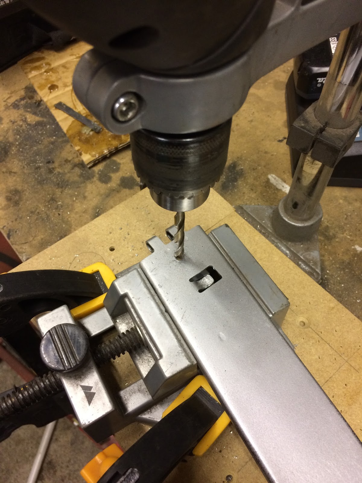
The only minor problem was that I had not cut this piece of flush when I separated it from the tunnel. This obviously meant that the plate was now slightly shorter than it should be, but I did not know by how much exactly. After a thorough rummage through the scrapped pan offcuts I reconstructed the front edge of the old pan. I then clamped the plate to the old floor pan scrap being sure to line up the bolt holes: 


I then clamped the reconstructed mess to the chassis tunnel in its original position for assessment. This enabled me to ascertain how much of the original reinforcement plate had been trimmed off: 


and here is the view from the underside:


Turned out that the plate was between 8-9mm short:


Armed with this new knowledge I created a reference drawing to act as a pattern (see the red outline) for when I make the replica part. I probably spent far too long producing this in Photoshop, but if it's worth doing then it is worth doing right: