Showing posts with label naps hat. Show all posts

Monday, 25 April 2016

Quickie: Pan-werk

Finished dressing the plug welds around the inner edges of the pans:


Then turned my attention to the weld bead that should run along the outer front section of the pan/naps hat joint. In typically obsessive Rhysos style, I wanted to ensure that I got this weld as close to 'factory' correct as possible. So I dug out the end of the naps hat from the scrap metal pile and quickly shot blast the topside to reveal the original factory weld:


It proved to be a handy visual aid and my attempt didn't come out too bad:


Yet again, this area won't even be seen when the car is back together, but it is all good practice and nurtures sound working habits (or at least that's what I tell myself!). Did the same on the other side of the car, but it appears I forgot to take a photo. It is just a mirror image of the pic above though, so this blog post probably doesn't need it.

Admittedly progress has stalled slightly in the garage following a spell of tool malfunction and misfortunate over the past couple of weeks. My trusty angle grinder, rotary tool and drill (how many is that now?!) all packed up in quick succession. I am just in the process of procuring some suitable replacements...

Wednesday, 5 August 2015

Napoleon fix-up (part 3)

I thought that repairing the passengers side of the Naps Hat would be a walk in the park. Well, that turned out not to be true! Here’s a quick review up to the point of the imploding headache...

This side of the Naps Hat was in a better condition than the driver’s side and so more original steel could be retained. With this in mind, I choose to make my cut just before the end tip starts to angle upwards and marked it up:


I cut out the pitted metal from one of the flanges (the other was solid so could be left):


I measured up and cut the corresponding section from the repair section and got everything trimmed flush. At this point I was thinking that everything was coming together perfectly and that I could have this done in no time:


However, as soon as I placed the repair piece onto the jig and moved it flush against the original steel my heart sank when it became apparent that there was a height difference of about 1.5mm:


I sanded the bottom of the repair section as there was a slight lip around the perimeter that was standing proud, but the overall difference this made was minimal. Looking at the cross-section of the repair section it was apparent that things were rather misshapen and I hoped that some bashing and manipulation I would be able to lower the profile and true-up the cross section. Two birds with one stone! Sadly, this just ended up making things worse. At this point the width was out by about 3mm and there was a visible taper when viewed from above! Damn these Klokker-shite aftermarket panels! Feeling deflated and frustrated I decided to sleep on the problem. With a rested mind and fresh perspective my solution was to add a little bridging section to replace the now distorted area. I trimmed the repro piece even shorter, to eliminate the dodgy section:


Then clamped it in place on the jig and made my measurements for the missing bridge section:


I bent this into shape using my former:


Here is the piece aligned against the jig with the first few welds in place. I think you can tell where I am going with this:


Ground and dressed:


With everything layed out on the jig, things were looking promising:


All welded in and the welds ground flush:


As with the drivers side, the last thing to do was to add a flange. I had to do this in two sections as my former was not quite long enough:  


Used my self devised gaffer tape and spray paint method to mark up the flanges and trimmed them to size: 


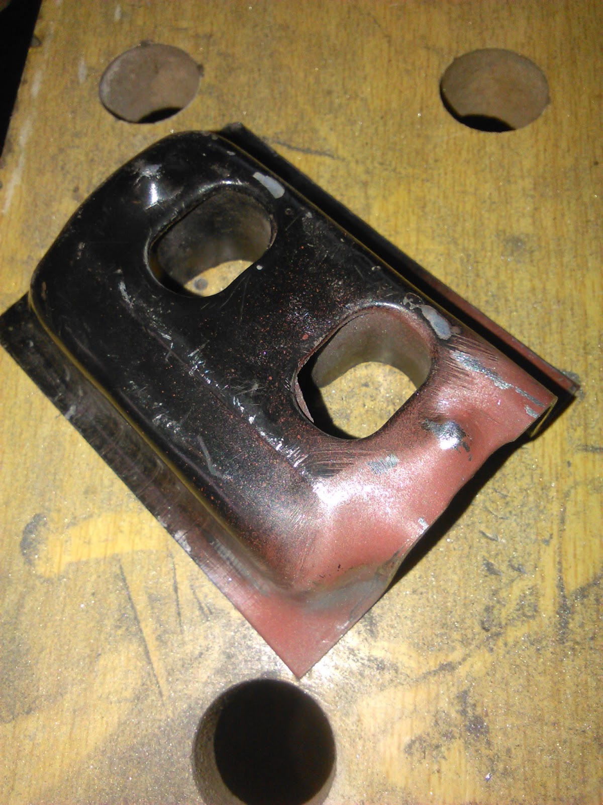
On a positive note, there was a silver lining to all this faffing. Because this repair procedure omitted the 3rd hole on the Klokker-shite piece, I was able to drill a factory correct 8mm hole in the correct position. Nobody will ever see it, but it makes me feel good to know that it is there:


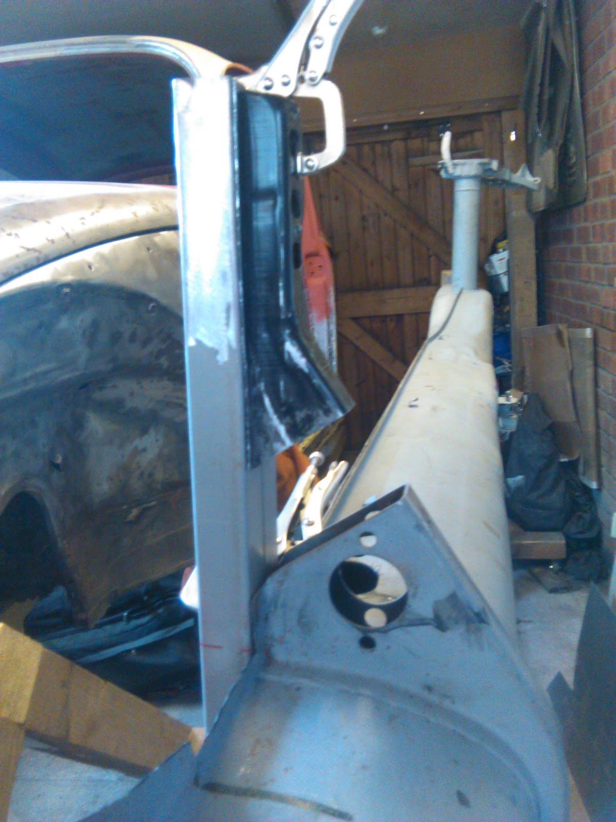
For symmetry's sake, I patched up the 3rd hole on the drivers side and also added the factory correct 8mm hole:  


I am delighted to announce that this concludes the Napoleon's Hat saga. Looking good as new:


Monday, 27 July 2015

Napoleon fix-up (part 2)

Using a strip of gaffer tape and spray paint, I marked up a suitable recess for my fabricated replacement flanges, ensuring that all the pitted metal on the inner side would be removed:


All cut and squared up:


I made some 90 degree flanges out of 2mm sheet. Took me a couple of attempts to get it right. Matching the curve radius was a challenge as it is gentle and not sharp. The solution was to bend them around a curved section of the left-over scraps of the repro Naps Hat:


I then finessed them to fit using my bench grinder. Trim, check, trim, check. One side aligned with the help of the trusty jig:


Fully welded and the weld dressed:


Same process repeated on the other side:


I got pretty good penetration for the most part, but there were small areas inside the naps hat that the weld had not reached. For piece of mind I added some reinforcing welds on the inside. These will not be seen and just add a little bit more strength: 


Here is the flange trimmed up and the welds ground level:


To get the correct placement of the hole(s) for the brake pipe to pass through, I cut out the corresponding sections from the repro panel to use as a template:


I then clamped them into place, aligning the master cylinder holes (which did not match up at all well, so I am glad that I have retained the original factory holes!):


I then drilled the holes out to just below the required size. I then used a cylindrical grinding stone mounted in the Dremmel tool to neatly widen the hole to the correct size using the repro section template to guide me:


And finally (drum roll please), the drivers side of Naps Hat completed and given a lick of primer:


It looks pretty sweet but is not totally perfect. There are a few areas where it appears that the alignment is slightly skewed (minor heat warping perhaps?), but I am optimistic that this will straighten up once the frame head bottom plate and floorpans have been welded into place. 

Coming up in Part 3: I repeat the whole process on the passengers side...

Wednesday, 24 June 2015

Napoleon fix-up (part 1)

A turning point has been reached as things are now very slowing starting to go back together! Because this blog post documents the first significant metalwork repair on the car, I have opted to covered it in step-by-step detail (don't worry, im not going to be as obsessive about describing every single minor repair in the future!). I shall publish this task in several parts as I progress, just to make it more digestible. 

Enough of the intro, lets jump into the action.... 

Repairing the Naps hat from the previous 'balls-up' has been weighing on my mind ever since the incident. You may recall from this previous post that I had ended up with a rather large gap between the old metalwork and the repair section due to poor judgment on my part. Since that time I have attempted to make various repair sections, but the arbitrary angles have caused nothing but frustration and poor alignment. I needed to simply things and approach this from a different angle (pun not intended). So, I decided to recut the remaining naps hat at a 90 degree angle to the diagonally sloping top edge. Here is the proposed angle marked with gaffer tape:


Checking for accuracy using a set square;


Once cut and neatened up I was confident that I had an angle that I could trust. It was a known quantity:


The main reason that I failed initially was that I had not focused on keeping the bottom edge of the repair straight and true. So, I figured that making a jig was the way to go this time. Essentially, I joined 2 pieces of scrap box section together using spot welds on one side and beads on the other. With the beads ground down and a lick of primer added I had a nice flat area:


I then made a paper template stencil with the bolt holes carefully mapped out to match the factory dimensions (with additional cross-hairs to visually assist with alignment). Also marked out some guides for aligning the jig with the chassis tunnel:


A quick spray of red primer to contrast against the grey:


....and the jig was good to go:


With the jig clamped into place on the chassis, I was provided with a solid foundation to work from. I trimmed up the end of the repro panel (again at 90 degrees to the sloping diagonal) and positioned it on the jig, clamping it into place. This allowed me to accurately assess the missing gap that I needed to fabricate:


Once measured up I cut out the repair section from fresh 2mm thick steel. Before bending the patch into shape, I knocked up a diy former to ensure that the outer profile of the piece would accurately match the original. I then put the whole lot into a vice and when I was sure everything was lined up correctly I proceeded to progressively tap the piece over with a rubber mallet:


 This created a good 90 degree bend with a suitable bend radius:


The fabricated piece all clamped up, aligned and ready for the welding to commence:


After countless hours playing with the settings on my new welder to ensure adequate penetration, I was finally confident to make the first tack weld of this resto - a significant milestone:


All of the tacks in place just prior to filling in the spaces in-between with a series of stich welds. To mitigate any heat warping, I filled up my compressors and used the air gun to blast a jet of cool air onto the hot welds:


Once it was all fully welded up I carefully ground the welds down dressed the area to make the new section blend seamlessly. Also rough cut the excess away from the bottom edge of the new piece:


Lining up the end section cut from the repro panel:


and here it is all welded in:


....and ground down nice & flush:


Seeing this section coming together has been really motivating and has boosted my confidence no end. You know, I reckon I can do this! 

Coming up in Part 2: I shall be cutting the bottom sections flush with the jig ready to accept newly fabricated flanges, drilling a few holes and more... Oooooh, the suspense!