
I began by drilling out the spot welds and separating the reinforcement section from the main panel. This gave me better access and allowed for a neater job:

On the main panel I smoothed out the unnecessary hump by simply cutting around it and welding in flat sheet steel:


These repros include an access hole to the heater channel. This was not something that mid-sixties cross members had, so I welded it up:


The rear edge needed a new profile adding to accommodate the correct upward angle of the heater pipe. After careful measuring and scribbling a few notes I mocked up a cardboard version of the hump I was trying to recreate:
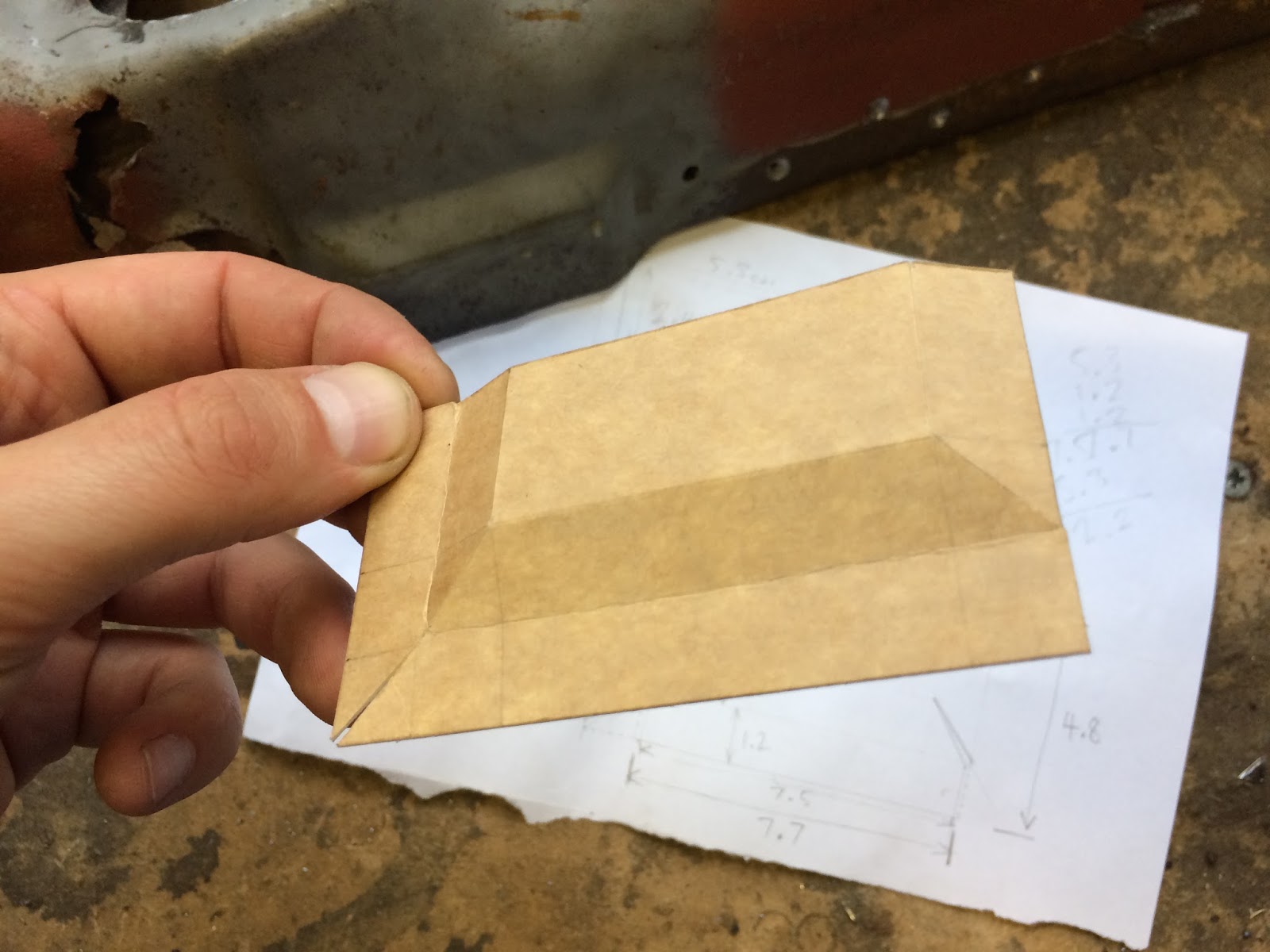
I then transferred the measurements to sheet steel and cut out the geometric net:

After some folding on the vice and a quick zap of the MIG welder to close up the slits:

Linished back and compared to the original:

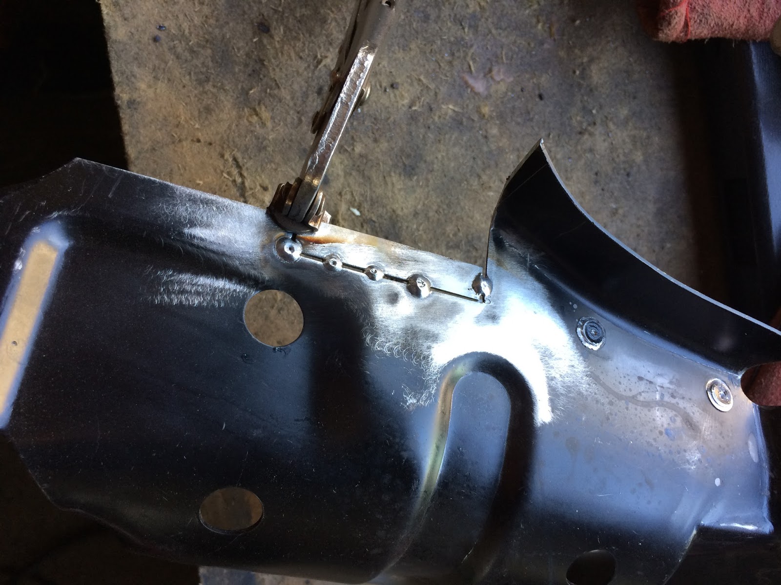
tacked into place on the cross member once the appropriate recess was measured and cut out:

After being fully welded, tweaked and dressed:

Just after the hump is a small section that is bent down on the original. I had to improvise around this section as access for clamping was tight. After some careful tapping with the hammer (remember that man light taps are better than fewer hard bashes), I got the 90 degree bend I was after:


Next task was to alter the heater pipe hole to the correct oval shape:


And trim the return flange to match the original (which terminates about halfway down):

At this point I roughly bolted up the heater channels to the pan and added the crossmembers. The fit wasn't as good as I had hoped and I was unsure at this stage if this was due to the restored pan being off or it the location of the mounting holes in the new panel were incorrect. After some head-scratching I discovered that the lower holes were not spaced apart close enough. There was a 5mm difference compared to the OG spacing.


After some Dremel tool action I had it all looking correct again:

I then shot blast the entire panel before plug welded the mounting reinforcement sections back into place:


Moving on to the thicker supporting rear panel that I removed in the first step, I proceeded to cut out the unnecessary hump and chopped off the rear section that I assume adds strength to the underside of the boot corners. However, this was not present on the originals so I determined that it was surplus to requirements:


Welded in some flat sheet to replace that bump and welded up the access hole that was also present on the main section:

I welded up this little join to add a bit more rigidity:

Shaped the mating flange that will eventually fix to the inner side of the rear wheel arch:
Shot blast the reinforcement panel and got it realigned the best I could to the main section. I decided not to plug weld the pieces together at this point, just in case I needed to adjust anything further down the road. So, here is the nearly finished article just prior to spraying with zinc primer:


Now to do the same on the other side...
Inspirational! Thank you for the detailed documentation of your project, it has helped me numerous times in the forensic reconstruction of my 66 sunroof bug. It would seem as though we draw very similar conclusions on how things should be in the restoration of our cars. Just as I am going through any given panel replacement I find myself frustrated at the lack of quality and accuracy of the repair panels, at which point I wonder to myself if you have been through the same -and sure enough.. :-)
ReplyDeleteHey Neil! Thanks for taking the time to comment. Pleased to hear my detailed posts are of use amongst my fellow dub restorers. My hope is that this blog will be a lasting resource for years to come and add something relevant to the VW community :-)
DeleteWith regards to the varying quality of panels; it is a challenge to do a decent resto with what is available off of the shelf, but I have found that it has forced me to get creative with what I can get my hands on and find viable solutions for myself. When that works out well (as was the case with these cross members) it gives me a deep sense of satisfaction.
Keep in touch and best of luck with that '66!
I'm really curious as to what you are using to bend the metal so accurately. The struggle I always have is to find a way to achieve multiple angles on a small piece of metal. For example on the 'hump' piece above you've got all sorts of reverse angles. Are you just using a vice and a hammer to bash it out or some sort of bending tool? Great work here and very inspirational stuff.
ReplyDeleteHi Matt, thanks for the kudos! In short, yes, all I use are basic hand tools. I don’t own any dedicated bending tools, so just improvise with what I have at hand.
DeleteI always use light taps with a rubber mallet to progressively bend the sheet metal over and have found that going slow, gentle and consistent leads to a more accurate result. I nearly always put lengths of angle iron into the vice to bend the metal around because the vice jaws themselves are too short and can leave unwanted impression marks on the work piece. Also, for areas where I cannot fit the mallet in I use a ‘drift’, which is usually a piece of scrap wood of appropriate thickness that fits the gap in question. I then tap on the wood and this in turn starts to bend the steel.
In terms of producing a more complicated piece with folds going in different directions; this does take some prior planning and a whole lot of thinking. Essentially, getting the order of the folds correct is key and it really is a puzzle where the solution is not immediately obvious. I usually test on rigid card before committing to steel as this is a quick and easy way to test an idea.
Hope the above pointers help!